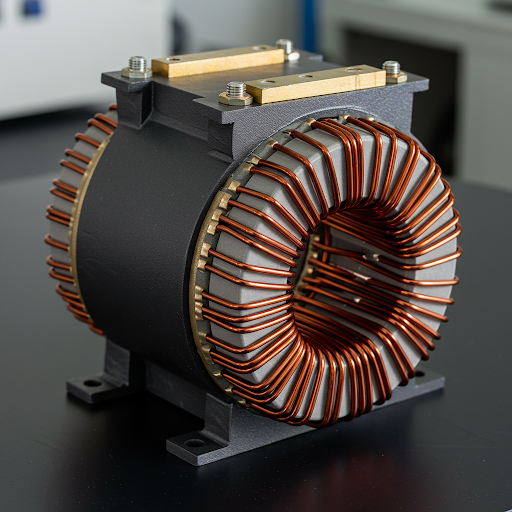
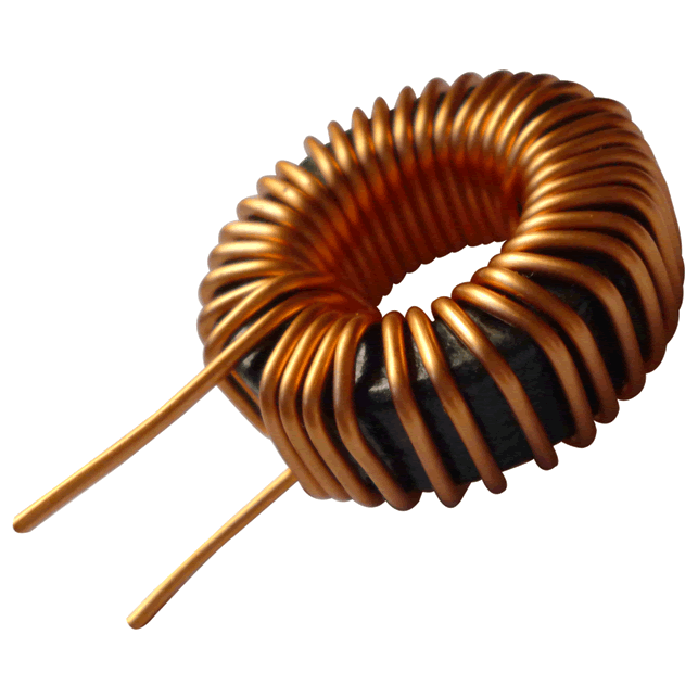
A 680µH, 12A inductor cannot be specified by inductance and current alone. The first question is whether 680µH must be maintained at 12A DC, or whether it is the nominal value measured with a small signal and no DC bias. Those requirements can lead to different cores, windings and dimensions. This guide checks an earlier design example and sets out the information needed to develop a testable specification.
Define the operating point before choosing a core
Record the following requirements before comparing designs:
| Requirement | What the specification should state |
|---|---|
| Inductance | Minimum and nominal values, tolerance, test frequency and voltage, DC bias and temperature |
| Current waveform | Average, RMS and peak current; ripple amplitude; startup and overload conditions |
| Switching conditions | Frequency range, applied voltage waveform and duty cycle |
| Thermal limits | Ambient temperature, cooling, allowed temperature rise and maximum winding/core temperature |
| Mechanical limits | Maximum wound dimensions, lead spacing, mounting and insulation requirements |
For illustration, assume a continuous current with a 12A average and triangular ripple of 4A peak-to-peak. The peak current is 14A, while the RMS current is:
I_peak = 12 + 4/2 = 14A
I_RMS = sqrt(12² + 4²/12) ≈ 12.06AThese are calculated example values, not measurements. They exclude startup and fault transients. Peak current is relevant to inductance retention and saturation; RMS current is relevant to heating. An Isat rating and an Irms rating describe different limits and must be read with the manufacturer's test criteria.[2]
Check the earlier T106-26 winding calculation
The previous article proposed a T106-26 core with approximately 65 turns. The Micrometals data sheet gives a nominal AL of 93nH/N², with ±10% tolerance under its stated 10kHz test conditions.[1] Using the nominal small-signal relationship:
L₀ = AL × N²
L₀ = 93 × 65² nH = 392.925µH ≈ 393µHThat result does not support a nominal 680µH design. Solving the same simplified equation for 680µH gives:
N = sqrt(680000/93) ≈ 85.5 turnsApproximately 86 turns is only a zero-bias starting estimate. Adding turns also changes the DC magnetizing force, winding length, resistance and available winding space. The core's bias characteristic must then be checked; a zero-bias AL calculation cannot establish inductance at 12A. The original combination of core, turns and wire therefore needs a complete redesign, not a turn-count correction alone.
Estimate energy and losses without treating them as test results
For an idealized inductor whose inductance stays constant, stored energy is:
E = ½ × L × I²
E = ½ × 680µH × (12A)² = 48.96mJThis is a useful scale estimate under the constant-inductance assumption. It does not prove that a particular core can retain 680µH at 12A. When inductance changes substantially with current, the magnetic characteristic must be included in the energy analysis.
As a separate resistance example, assume a winding DCR of 10mΩ at operating temperature. With the example waveform above, the resistive baseline is:
P_resistive ≈ I_RMS² × DCR ≈ 1.45WThe resistance is an assumption, not a T106-26 winding specification. This estimate omits additional frequency-dependent winding loss and core loss. Neither total loss nor temperature rise follows from it alone. Use material loss data for the actual excitation, assess the winding at operating frequency, and verify heat removal in the intended assembly.[2][3]
Compare complete magnetic designs
Powder cores, gapped ferrite cores and suitably designed nanocrystalline cores are candidates to investigate. A material name does not establish which assembly is smallest or most efficient.
| Candidate | Evidence needed before selection |
|---|---|
| Powder-core design | Exact material and geometry, AL tolerance, DC bias characteristic and loss data |
| Gapped ferrite design | Material grade, effective gap, inductance at bias, winding arrangement and gap-related heating |
| Nanocrystalline design | Manufacturable core/gap specification, bias and loss data, insulation and mounting details |
Compare wound assemblies under the same current waveform, temperature limit and mechanical envelope. The earlier volume estimates and efficiency ranking are removed because they were not supported by comparable calculations or measurements.
Prepare a sample verification plan
- Obtain the current core data sheet and a winding drawing with wire, turns, insulation and lead details.
- Measure inductance under the specified small-signal conditions, then check it with the required DC bias and relevant temperatures. Define the minimum acceptable value.
- Verify current waveforms in the intended circuit, including startup and specified overload cases. Confirm that inductance reduction does not cause an unacceptable current slope.
- Measure DCR at a stated temperature and confirm steady-state winding and core temperatures in the actual mounting and cooling conditions.
- Repeat the relevant checks across the allowed input, load and component-tolerance range before approving the design.
The Magdir current check and copper-loss calculator can support preliminary comparisons. Their estimates should be checked against the manufacturer's data and sample results.
Sources and revision
- Micrometals T106-26 data sheet, revision 20190524, page 1: AL, test conditions and DC bias characteristic.
- Coilcraft: Current and Temperature Ratings, sections on current definitions and measurement conditions.
- Coilcraft: Selecting the Best Inductor for Your DC-DC Converter, sections on inductance, resistance and current ratings.
Revised on 2026-10-23 from manufacturer documentation, with AI-assisted editorial and language review. This revision corrects the winding calculation and replaces unverified finished-design claims with a calculation and verification workflow. No prototype or laboratory results are claimed; an approved 680µH, 12A assembly still requires sample verification.