
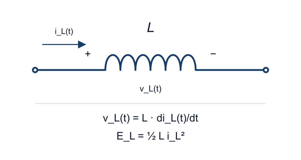
An inductor is a passive component that stores energy in a magnetic field. Its defining circuit property is the relationship between voltage and the rate of change of current. That makes it useful for controlling current ripple, transferring energy in switching converters and setting the frequency response of RF circuits.
The component is an inductor; its inductance, L, is a quantity measured in henries (H). A value such as 10 µH describes one characteristic, not a complete component specification.
How an inductor behaves
For an ideal, linear inductor with constant L, using the passive sign convention—current enters the terminal marked positive:
v_L = L × di/dt
ΔI = V_L × Δt / L
E_L = ½ × L × I²Here, v_L is the voltage across the ideal inductance. The winding's resistive voltage drop is separate. The current changes according to the voltage applied; it cannot jump instantaneously with finite voltage in this model. Opening a real current path can therefore produce a voltage transient. The underlying self-inductance and energy relations are covered in OpenStax §14.2 and §14.3.
Calculation example, not a measurement: assume L stays at 10 µH, with 1 V across the ideal inductance for 10 µs. The current increases by 1 A. At a separate operating point of 2 A, the stored energy is 20 µJ. These results do not establish a real part's saturation capability or temperature rise. If inductance changes appreciably with bias, a constant-L calculation needs a more suitable magnetic model.
Application labels and construction describe different things
“Power inductor” and “RF inductor” describe intended uses. A power design often emphasizes current waveform, bias-dependent inductance and losses; an RF design also needs inductance, Q and impedance at the signal frequency. “Air core,” “ferrite core,” “wirewound” and “multilayer” describe construction. They are not interchangeable performance grades.
Shielding and package dimensions also matter, but a shielded part does not eliminate every coupling or layout problem. Start with the circuit requirement, then compare parts under matching conditions. Coilcraft's selection guide explains why a calculated inductance must be followed by component-level checks.
Read these specifications together
| Specification | What to check |
|---|---|
| Inductance and tolerance | Test frequency, signal level, bias and temperature; obtain the relevant L-versus-current curve. |
| Saturation current, Isat | The stated reduction in L, reference conditions and behavior at the required peak current. |
| Heating-current rating, often Irms | Allowed temperature rise, ambient, board and test method; include the actual waveform's losses. |
| DC resistance, DCR | Typical versus maximum value and reference temperature. |
| Self-resonant frequency, SRF, and Q | Impedance and loss behavior at the intended frequency, not just one catalog number. |
| Mechanical information | Size, height, pads, mounting and surrounding circuit constraints. |
Isat and Irms describe different limits; neither should be substituted for the other. Coilcraft defines its Irms test using a DC current producing a stated temperature rise under specified conditions. A switching waveform can add losses that this test does not represent. See its current and temperature rating definitions.
For example, 2 A RMS through a winding resistance of 0.05 Ω gives a resistive-loss estimate of 0.20 W using I_RMS² × DCR. This assumes that resistance value applies at the operating condition; it excludes additional AC winding and core losses and does not predict temperature by itself.
A reproducible way to check a candidate
- Record the circuit frequency, current waveform, peak and RMS current, ambient temperature and space limits.
- Check the manufacturer's exact part number and suffix, including measurement conditions and bias curves.
- For an incoming-value check, reproduce the datasheet test conditions. Separately evaluate behavior at the application's frequency and bias.
- Record the instrument, fixture and compensation, test level and temperature. A low-current LCR reading alone does not establish high-current performance.
- Check the assembled circuit for waveform, loss and temperature, then retain the results with the part revision.
Coilcraft's application-frequency measurement note explains why frequency and fixture differences can change the measured result. Near self-resonance, a simple ideal-inductor model is especially inadequate.
For the next step, use the inductor current check, locate the original document in the datasheet directory, or compare circuit roles in inductors versus capacitors.
Sources and revision note
The linked textbook sections establish the ideal relationships; the manufacturer notes supply rating and measurement context. The numerical examples are independently calculated illustrations, not reported tests of a particular component.
Revised 2026-10-24: replaced unsupported personal experience and production anecdotes with sourced definitions, explicit assumptions and a checkable workflow. Prepared with AI assistance; no independent engineering or native-speaker review is claimed. The original publication date and URL are retained in the editorial record.
