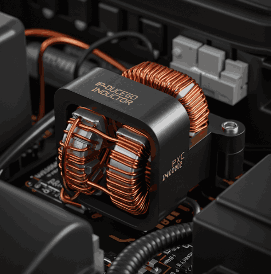
A hot automotive power inductor needs a loss and temperature investigation before a component swap. The cause may be winding loss, magnetic-core loss, heat from nearby parts or an inadequate cooling path. Several can act together. This guide provides a calculation and a controlled diagnostic sequence; it does not report a tested vehicle design or predict battery range, life or safety outcomes.
Separate heat generation from heat removal
TDK's power-inductor application note, in the section on load and frequency, distinguishes winding and core losses. Their relative importance depends on the actual waveform, frequency, material and construction. Frequency alone cannot identify the dominant loss, and low-frequency core loss should not simply be declared negligible.
| Contribution | Evidence to collect | Common interpretation error |
|---|---|---|
| Winding resistance | Current waveform and DCR at the evaluated winding temperature | Using cold DCR throughout the calculation |
| Additional AC winding loss | Frequency, ripple and a suitable large-signal loss model | Treating low-signal ESR as valid under every bias condition |
| Core loss | Material or part-specific data at the relevant excitation and temperature | Selecting by permeability alone |
| Heat exchange with the assembly | Board, enclosure, airflow and nearby heat-source conditions | Attributing every temperature increase to inductor loss |
An RMS-current calculation using DCR includes the base resistive contribution of the entire waveform. If the loss model also provides AC winding loss, establish whether that number is additional to this baseline or already includes it. Do not count the same ripple loss twice.
Calculate a stated winding-loss example
Assume continuous triangular ripple with 4 A DC and 2 A peak-to-peak ripple. Let R_25 = 0.020 Ω at 25°C and assume the winding is at 100°C. Use α_25 = 0.00385/°C, the approximate copper coefficient used in Coilcraft's current and temperature note, “DC Resistance vs. Temperature,” Eq. 4. These are independent example inputs, not a catalogue row or measurements.
For zero-mean linear triangular ripple, averaging its squared value over a period gives ΔI_pp²/12. The cross term with DC averages to zero, so I_RMS² = I_DC² + ΔI_pp²/12.
R_100 = R_25 × [1 + α_25 × (100 − 25)] = 0.025775 Ω
I_peak = I_DC + ΔI_pp / 2 = 5 A
I_RMS = √(I_DC² + ΔI_pp² / 12) ≈ 4.041 A
P_R,100 = (4² + 2² / 12) × 0.025775 ≈ 0.4210 W
P_R,25 = (4² + 2² / 12) × 0.020 ≈ 0.3267 W
The example shows how using cold resistance understates this resistive term. It does not show that 0.4210 W causes a 100°C winding: temperature was an assumed input. Additional AC winding and core losses remain uncalculated. Use the actual waveform if it contains skipped pulses, discontinuous intervals or current-limit events; the continuous-triangle formula then may not apply.
Build a measurement record before changing hardware
Capture input and output voltage, load, switching frequency and mode, current waveform, peak and RMS current, and local ambient conditions. Record the full part number, board revision, copper layout, enclosure, airflow, nearby heat sources and thermal measurement location. State when thermal steady state was reached and use a documented, calibrated measurement method.
Keep surface and winding temperatures distinct. An instrument reading at one surface location does not establish the winding hot spot. Record sensor placement and measurement limitations so repeated tests are comparable. Coilcraft's rating note describes its own surface-temperature measurement setup; that setup is not automatically the setup used by another manufacturer or by your board.
Compare cases with one planned change at a time. Increasing load, changing frequency or improving cooling can help separate possible causes, but each also changes operating conditions. Check current waveform and control mode again before attributing a temperature change to one loss mechanism.
Match the corrective action to the evidence
If resistance-related loss dominates, compare candidates using operating-temperature DCR, required inductance, size and current capability. A lower DCR alone does not establish lower total loss. If frequency-dependent loss is important, use part-specific data or a validated model at the actual ripple and bias conditions.
Changing inductance or switching frequency can change ripple, loss, dynamics and EMI simultaneously. Recheck the controller requirements and full operating range. If the cooling path is limiting, evaluate board copper, placement, airflow or an approved thermal interface in the actual assembly. Open construction, extra winding layers, a heat sink or potting is not universally cooler.
Coilcraft's loss and temperature-rise note, especially “Losses and Temperature Rise,” explains why heat flow depends on construction and assembly conditions. A relation such as ΔT ≈ P × R_th,eff is useful only with a justified effective thermal resistance for that configuration. Do not import an IC junction-to-case value or a generic range into an inductor calculation.
Recheck current ratings and application limits
Isat is defined by a specified inductance reduction; Irms uses a specified heating criterion. Read the exact part's conditions and temperature limits, including whether self-heating is included. Neither name alone establishes acceptable operation under switching ripple. Check startup, overload and protection recovery separately.
Do not infer an approved lifetime, permanent demagnetization or a battery fire outcome from a temperature observation alone. Any safety-function decision, protection threshold or vehicle acceptance needs responsible automotive engineering review. Verify the proposed change electrically, thermally, mechanically and for EMC before release.
Use the inductor current check for preliminary calculations and the automotive reliability guide to organise validation evidence.
References and revision
The three manufacturer notes linked above support loss categories, rating definitions, the copper-resistance approximation and thermal-model limitations. No hardware test or independent vehicle qualification is claimed.
Revised 2026-10-27: removed unconditioned material, cooling, lifetime and hazard claims; added a reproducible waveform calculation and a measurement-led diagnostic sequence. Original URL and publication date remain in the editorial record. AI editorial self-review completed; independent native-speaker engineering review and application-specific safety acceptance have not been performed.