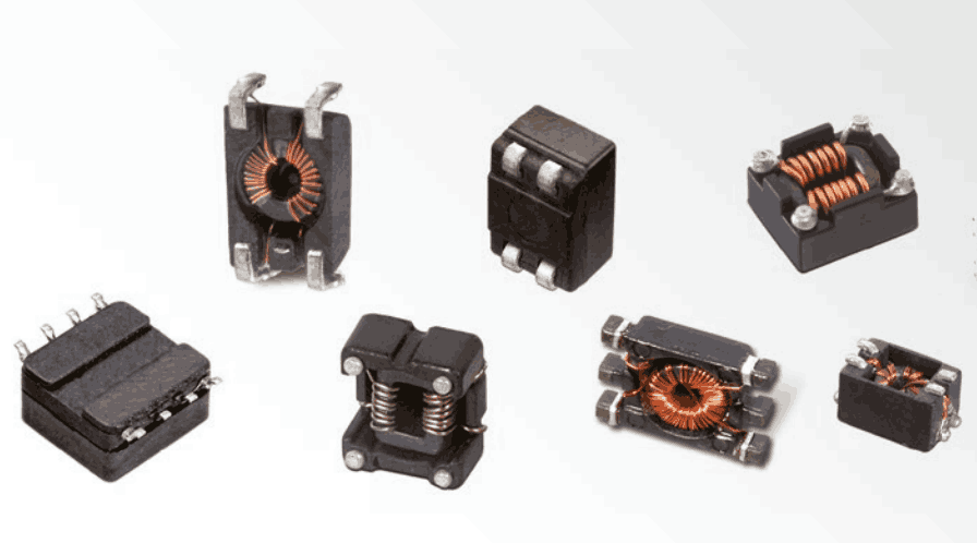
Würth Elektronik's 744725 is a design-kit order code, not a single choke with one electrical specification. Use the assortment to compare candidates, then choose by the complete component order code and its current datasheet. A kit described for USB, CAN or data lines does not establish that every included part suits every version of those interfaces.
Start with the kit and identify the actual part
The manufacturer's 744725 kit page lists several common-mode choke families. Treat its contents as a source of evaluation samples. Confirm the supplied assortment and the exact part markings before using a sample result in a bill of materials.
The broad legacy table on this page has been replaced with one traceable example: WE-SL5, order code 744272121. Values from different families, revisions or winding arrangements should not be combined into a substitute specification.
Read values together with their conditions
The following entries are from 744272121, Rev. 007.000, 2026-02-06, page 1. Unless otherwise stated, its electrical test conditions are +20°C and 33% RH.
| Parameter | Datasheet entry | Condition or interpretation |
|---|---|---|
| Inductance L | 120 µH, ±40% | 100 kHz / 100 mV |
| Maximum impedance Zmax | 450 Ω, typical | 10 MHz; not a guaranteed minimum across a band |
| Impedance at 100 MHz | 400 Ω, typical | Frequency-specific value |
| Rated current IR | 3000 mA, max. | ΔT = 40 K; this is not an Isat declaration |
| DC resistance RDC | 0.025 Ω, max. | Keep resistance separate from high-frequency impedance |
The older table's 460 Ω and 2500 mA for this order code do not match the cited revision. Do not carry those figures forward without a dated manufacturer document supporting them. Likewise, a two-winding schematic does not mean the listed inductance can simply be doubled for the installed circuit.
Check the wanted signal as well as the noise
Page 2 of the same PDF shows common-mode and differential-mode characteristics. Use both: the unwanted noise and the wanted differential signal impose different requirements. The Coilcraft high-speed-interface selection note explains why differential attenuation must be checked before choosing common-mode filtering performance.
Record the actual interface, signaling conditions, termination, noise frequencies and allowable signal degradation. Compare the relevant frequency curves or available S-parameters, then check the assembled link. Neither nominal inductance nor Zmax alone predicts insertion loss in a particular cable, connector and PCB. Typical curves describe a reference behavior, not a universal compliance result.
Account for both windings in a loss estimate
This is a simplified calculation example, not a measurement. Assume each line carries 1 A DC and each winding has 0.025 Ω resistance under the evaluated reference conditions. For the forward-and-return path:
R_loop = R_1 + R_2 = 0.025 + 0.025 = 0.050 Ω
V_drop = I × R_loop = 1 × 0.050 = 0.050 V
P_R,total = I² × (R_1 + R_2) = 1² × 0.050 = 0.050 WThe equal opposing line currents do not remove winding resistance losses. This estimate omits resistance changes with temperature, additional AC losses and magnetic-core losses. It cannot predict temperature rise or prove that the current rating is met on your board. Recalculate for the actual currents and check the manufacturer's thermal limits separately.
Make the sample comparison reproducible
- Record the full order code, datasheet revision, winding connections and footprint.
- Set signal-integrity and noise criteria before comparing samples; retain the unfiltered baseline.
- Keep PCB, cable, termination and instruments consistent, documenting any change.
- Measure the relevant signal behavior, EMI response, voltage drop and component temperature at the intended operating conditions.
- Select the part only after checking electrical, thermal and mechanical requirements; retain open questions for the responsible engineers.
The datasheet directory helps locate documents. The inductor fundamentals guide explains basic terminology; it does not make a common-mode choke interchangeable with an energy-storage inductor.
References and revision
The linked kit page establishes the assortment's identity, the exact-part PDF supplies the tabulated values and curves, and the application note supports the signal/noise selection method. These sources do not establish that this part passes a particular interface or equipment test.
Revised 2026-10-26: clarified the kit number, removed the mixed unverified model table, added revision-bound parameters and a two-winding loss example. AI-assisted editorial review; no independent native-speaker engineering approval or hardware test is claimed. The original URL and publication date are retained in the editorial record.