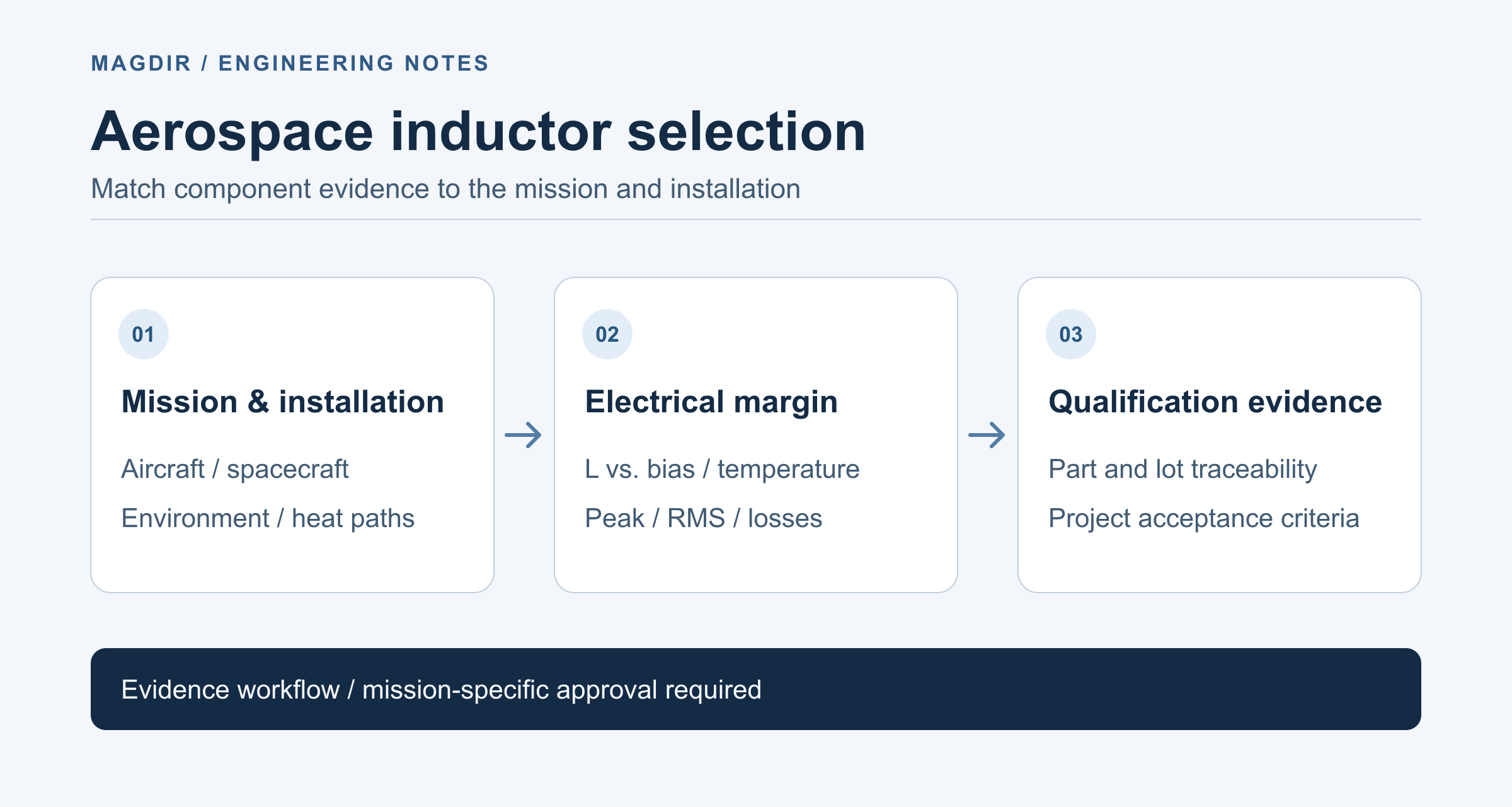
Selecting an inductor for aircraft or spacecraft begins with the mission and installation, not a universal “aerospace-grade” label. The part must retain the required electrical behavior under the defined stresses, and the supporting evidence must match its part number, construction and procurement history.
This is a source-based selection guide, not an airworthiness finding, flight qualification or mission approval. The responsible parts, reliability and system engineers must establish the applicable requirements and acceptance criteria.
Separate airborne equipment from a spacecraft mission
Specify where the inductor is installed, the power-converter or signal-circuit function, operating modes, fault consequences and mission duration. An aircraft installation and an unpressurized spacecraft assembly do not have the same environmental assumptions.
RTCA's official DO-160G Environmental Qualification Form description concerns equipment tests and their applicable environmental categories. It is not a universal qualification mark for an individual inductor. RTCA's DO-160 overview also identifies DO-160G and its supporting material; select the required revision and categories through the equipment's actual approval process.
For space parts, NASA GSFC's EEE-INST-002 page separates selection, screening, qualification and derating. The public page labels its posted version April 2008 with Addendum I. Here it illustrates a GSFC parts-assurance framework; it is not presented as a requirement automatically binding every mission, and no numerical derating table is applied.
Ask for data that match the stress being evaluated
| Engineering question | Evidence to request |
|---|---|
| Will sufficient inductance remain? | L and tolerance at the relevant frequency, DC bias and temperature; check the peak operating current against the manufacturer's biased-inductance data and saturation criterion. |
| Can the installed assembly remove the losses? | DCR at the evaluated temperature, additional AC winding and core losses, and the real heat path. |
| Can the construction tolerate the environment? | Project-defined mechanical, thermal and material requirements, with applicable test configuration and acceptance criteria. |
| Does the evidence cover the delivered parts? | Full part number, drawing and material revisions, supplier, lot traceability and controlled changes. |
Isat and Irms describe different limitations. Coilcraft's current and temperature ratings explains the inductance-drop criterion for Isat and its DC temperature-rise basis for Irms. Neither a room-temperature current value nor a magnetic core's Curie temperature establishes the operating range of the complete component.
For a component operating in vacuum, do not carry an air-cooled test-board temperature rise into the flight thermal model unchanged. NASA's Thermal Control chapter, §7.2.1 explains the absence of convection in vacuum. Evaluate the assembly's conductive and radiative heat paths instead. A pressurized enclosure needs its own stated thermal assumptions.
Make margin calculations explicit
The following inputs are hypothetical, not a manufacturer's data or test results. At a selected 100°C condition, assume a candidate has Isat of 4.0 A under a specified inductance-drop criterion and DCR of 0.060 Ω. Assume the circuit's peak current is 3.0 A and RMS current is 2.5 A.
I_peak / Isat = 3.0 / 4.0 = 0.75 = 75%
P_R = I_RMS² × DCR = 2.5² × 0.060 = 0.375 W
The ratio describes only those assumed inputs. It is not a NASA or RTCA acceptance limit, and “75%” does not demonstrate compliance with a project's derating policy. Verify the required inductance at the actual peak current, including tolerances and transients. The resistive-loss estimate omits extra AC winding and core losses and cannot establish the component temperature or life.
Keep qualification, screening and acceptance distinct
A useful review package must identify what each activity demonstrates. Qualification evidence addresses a defined design and environment; screening and lot acceptance serve different purposes. A test report without part identity, conditions and pass/fail criteria cannot substantiate a general reliability claim.
Do not infer radiation endurance, outgassing suitability or long service life from a material name or passive-component designation. Ask the mission specialists what evidence is required for the actual materials, construction, location and mission profile. This article supplies no universal radiation dose, extreme-temperature capability, lifetime or converter-efficiency guarantee.
For mechanical evaluation, preserve the mounting, board support, orientation, test profile and pre/post electrical measurements. For electrical faults, evaluate open circuit, short circuit and parameter change in the system context. An inductor alone does not establish short-circuit protection; the surrounding protection circuit must be assessed.
Turn the selection into a traceable decision
- Approve the mission and installation requirements, including electrical waveforms, environment and consequences of failure.
- Obtain the complete component definition and compare temperature- and bias-dependent data with the worst-case operating points.
- Apply the project's actual derating rules, recording the governing document, revision, parameter definitions and unresolved assumptions.
- Agree the qualification, screening and acceptance plan before interpreting reports as evidence for delivered hardware.
- Retain calculations, test configurations, lot records, deviations and specialist approval with the final parts list.
The inductor current check can support preliminary comparisons. Use the datasheet directory for candidate documents and the inductor fundamentals guide for electrical terminology. These resources do not grant flight approval.
References and revision
The linked RTCA and NASA pages establish the scope of their frameworks; the NASA thermal chapter and Coilcraft note support the stated physical and rating distinctions. Public summaries were reviewed, not a complete contractual standards set. The actual mission specification and qualification evidence still require specialist review.
Revised 2026-10-25: removed unsupported extreme-temperature, radiation, lifetime and efficiency figures; separated aircraft and spacecraft contexts; added a reproducible, explicitly hypothetical margin example. AI-assisted editorial review only, with no independent expert approval or hardware test claimed. The original URL and publication date remain in the editorial record.